


-
Fibretool invites you to visit ANGACOM2024
2024-03-31
1051
-
2023-11-08
1206
-
CIOE 2023 (The 24th China International Optoelectronic Exposition)
2023-08-16
1278
-
VIETNAM ICTCOMM Exhibition 2023 is coming to you!
2023-05-29
1474
-
How to Choosing a Fiber Optic Tool Kit?
2021-08-14
2107
-
Media Connector for Fiber Optic Cable
2022-11-04
2241
-
Fibretool CIOE September 16-18, 2021.
2021-09-07
1925
-
Testing Optical Fiber Cabling Terminated with CS Connectors
2022-11-04
1570
-
Fibretool 21th CIOE Invitation
2019-08-01
3681
Testing Optical Fiber Cabling Terminated with CS Connectors
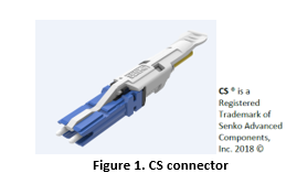
TIA has started a new project for a Fiber Optic Connector Interface Standard (FOCIS-19 that details the CS connector. This connector is a duplex ceramic ferrule connector smaller in size than two LC connectors and takes advantage of the need for higher density in data centers. The ferrules are 1.25 mm (See Figure 1). The initial offering is with single-mode fiber.
Testing the CS connector on patch cords or installed cabling presents a challenge. Since this is a new connector, test equipment suppliers have not yet responded with test equipment that has an CS interface. If your power meter does not have a CS interface port, you may have to do the 3-cord method. This could apply to an MTRJ, keyed LC (that we are seeing in some government applications) or an MPO connector. On the light source, a duplex interface may add complexity.
As an alternative, testing can be done with breakout cords using a light source and power meter (LSPM), an optical loss test set (OLTS), or with an optical time domain reflectometer (OTDR).
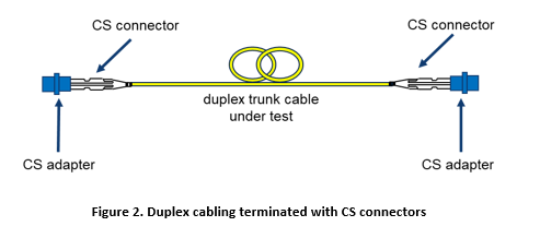
Before the 3 test methods are explained, let’s first look at what is being tested (see Figure 2.) Note that break-out or hybrid cords are shown with a neutral grey color.
LSPM
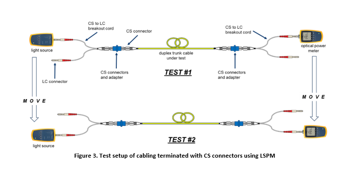
Using a light source and power meter, as shown in Figure 3, an attenuation measurement can be made. In this example, the light source and power meter have an LC interface. The cabling under test is terminated with CS connectors and adapters. A CS to LC breakout cord is needed on either side of the trunk cabling that is under test.
The goal is to measure the attenuation for one fiber (TEST #1) then for the other fiber (TEST #2). In all cases, after making a reference measurement (i.e. 0 dB) while using the 3-cord method, the launch cord should not be disconnected from the light source regardless of which test method is used. In Figure 3, TEST #2, a second reference measurement must be made before the cabling is measured for attenuation.
The optical power meter will measure and report attenuation as a positive value. If the light source is moved as shown in Figure 3, the reference must be reset. The 3-cord method will be explained in detail later.
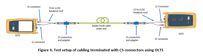
OLTS
The OLTS is designed for duplex testing and greatly reduces test time. For the OLTS, it is only necessary to test in the direction of transmission. In this case, only one test is needed. The test cords are 2 meters in length. Figure 4 shows the desired setup for testing with an OLTS but as will be shown later in the 3-cord method procedure, additional test cords are needed.
OTDR
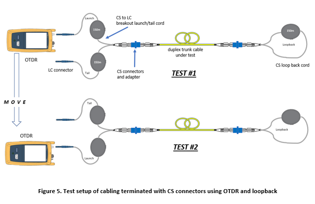
For the OTDR test method, the breakout cords (launch and tail cords) should be at least 150 meters for single-mode. The launch and tail cords create optical separation between the OTDR emitted pulses detected at the instrument and the connectors. In this way, an attenuation and return loss measurement can be made at the CS connectors. To reduce test time and to make a better measurement, a bidirectional test using a loopback cable can be done in two steps (see Figure 5.) The nice thing about the OTDR method is that a reference measurement is not needed.
3-Cord Method
Although Fluke Networks recommends the 1-cord method for setting the reference, testing cabling with CS connectors is not possible using this method. An alternative is to use the 3-cord method which can be described in four steps.
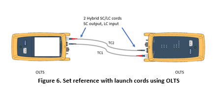
The first step is to set a reference with the launch cords (TC1 and TC2) using the 1-cord method (see Figure 6). The purpose of this first step is to prepare for the second step – to verify the condition of the test cord end face connections (launch and receive cords).
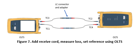
The second step is to disconnect the launch cords (TC1 and TC2) from the power meters on the OLTS (not the source) and add the receive cords (TC3 and TC4) to the power meters. Next, couple the launch cords to the receive cords (TC1 to TC4 and TC2 to TC3). Make a measurement and verify low loss (e.g., 0.25 dB) for each pair. Then, set the reference to 0 dB (see Figure 7). The reason another reference measurement is made during this step is because the loss of the substitution cord must be verified in the next step.
A suitable 2-meter substitution cord is used in the next step (see Figure 8). It is important that the substitution cord has been inspected, cleaned, and verified for low loss. A substitution cord with high connector loss could result in a measurement where the cabling under test appears to have negative loss (e.g., gainer). Make the reference measurement with the substitution cord as shown in Figure 8.
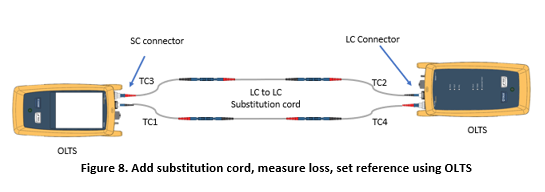
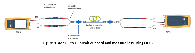
After the reference measurement is made, without disconnecting anything attached to the OLTS, remove the (duplex) substitution cord. In place of the substitution cord, add the CS to LC break-out cord and attach both ends of the CS ends of the break-out cord to the cabling under test as shown in Figure 9. The measured attenuation is the loss of the fiber in the cabling plus the loss of the two connectors in the cabling, minus the substitution cord loss of the two connectors.
Summary
Installed cabling terminated with single ferrule connectors such as SC, LC, FC, etc. can usually be tested using the 1-cord method. However, multi-fiber connectors such as the CS connector cannot be tested using the 1-cord reference method. The 3-cord method is an acceptable alternative when using LSPM or OLTS. The OTDR method can also be used and does not require a reference method. The OLTS is the preferred tester for duplex testing. The OLTS is easier to use because it can do all the calculations for you, has a built-in guide wizard, is faster and easier for duplex testing, and allows merging of test results.

ISO 9001:2015

Unit 7-8,11F,Lane 2653,Peace Plaze,
Hunan Rd.,Pudong,Shanghai,CN-201315


+86 21 5824 3122
+86 21 5824 3052
Copyright 2023 ©Shanghai Fibretools Technology Co.,Ltd. All Rights Reserved. 沪ICP备07003305号

Operating Guide
On Site Guide